OPTION 1
Set the PELLIPSE variable to 1 and draw an ellipse. The default is set to 0 which draws an accurate ellipse object. Setting the variable to 1 lets you draw an ellipse made up of series of arcs forming a Polyline. Polylines can then be converted to Civil alignments.
However, ellipse drawn this way won’t result to the correct shape. From visual inspection, the difference between the true ellipse and polyline ellipse is noticeable near the ends of the major axis.
OPTION 2
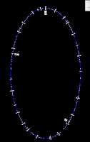
Use the DIVIDE command to add Autocad points along the true ellipse. The more segments, the better.
Convert the AutoCAD points to COGO points.
Connect the “dots” using SPLINE. Type 'PN to call up the Point Number transparent command. Type the point number range. In my example, 1 – 120 and close the spline.
FLATTEN the closed spline but don’t remove hidden lines.
This will convert it to a series of connected arcs that follow the ellipse more precisely.
Finally convert the polyline to a Civil 3D alignment. It won’t be laser accurate if you zoom in and look closer but isn’t too far off compared to the first option.

Have a great weekend!!


No comments:
Post a Comment